Building a Calibration Table in Ezchrom (with screenshots)

This is a quick guide on how to build a calibration table in Ezchrom.  This should work in both Ezchrom Elite as well as Openlab Ezchrom.


1.  Have your method(s) that you would like to use saved and ready.  This first step is pretty straightforward.  You want to have a good idea of what your method parameters will be before you start building your calibration table.

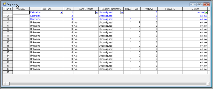
2.  Set up a sequence of runs with your calibration standard(s).  In my example, I am using three levels of calibration.  If you expect your samples to be within a certain range, you want to select standard concentrations that will cover that range.  So, if my samples will have a concentration in a range of 50-75 ng/ul for example.  Then I would want to choose standards at 30, 60, and 90 ng/ul, perhaps.   Whichever calibration levels you choose to have, make sure you have them ready and know which vials they are in, and designate that in your sequence table.

2017-10-10_7-21-11

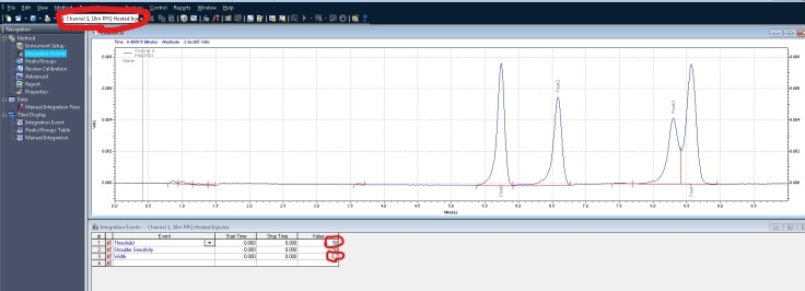
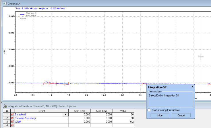
3. Integrate your peaks.  Make sure you have the proper channel selected at the top, for the chromatogram that you want to adjust.  Next select integration events, the two values you want to focus on at first are threshold and width.  You can keep clicking analyze to see how your changes affect the integration.  It’s more or less a trial and error approach.  There are several other options you can continually add to your integration table to fine tune your chromatogram.

Inked2017-10-10_7-24-46_LI

In this example, I would like to remove some non peaks at the start of the chromatogram.  I can click on integration off, on the bottom of the screen.  It then wants you to click on the chromatogram where you want to start the cut off:


2017-10-10_7-24-56

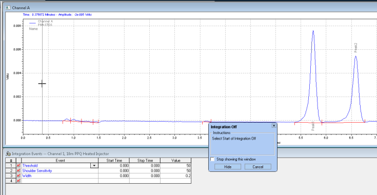
Next it wants you to click where you want the integration off event to stop:

2017-10-10_7-25-04

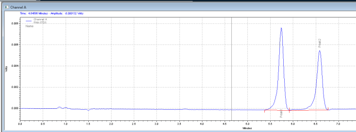
After you analyze, you get the chromatogram with the unwanted peaks removed:

2017-10-10_7-25-58

4.  Calibration.  After integrating your signals, the next step is calibrating.  Peak selection can be done graphically on the chromatogram.  You can click on the icon to define peaks, click at the start of the peaks, then click at the end of the peaks.  The peak table will come up, and you can name the peaks, and designate their concentrations.

2017-10-10_7-26-18

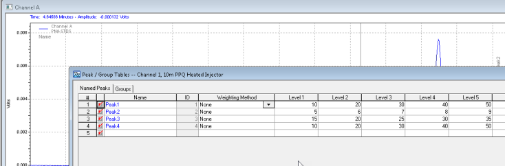
Save these changes to your method, and the software will now calculate the amounts of your unknowns based on your calibration table!

Can’t Communicate with my Instrument (GC or LC)!

2016-05-01_18-28-36


There’s nothing like  preparing your samples and starting chemstation, only to see “instrument offline”.  There are some basics that can be checked that may be the solution if you are having this problem.

IP addresses:

You always want to start here.  A 68/7890 GC, as well as 1100-1290 LCs use LAN communication for the most part.  The main idea being, is the ip address of the instrument and the ip address of the pc compatible?  You want the ip address to match up until the last set of numbers.  For example:  if the gc is 10.1.1.101, the pc needs to be 10.1.1.x.  If the LC is 192.168.254.11, the pc needs to be 192.168.254.x.  With “x” being any digit from 1 to 255.

How can I check the ip address of the GC?  This is pretty simple, on the majority of these GCs you can find out by hitting options, then communication on the gc front panel.  From here you can see what the address currently is, and you can also change it as well.

The LC is not as straight forward, but the default is 192.168.254.11.  You can also connect the gameboy to the module and view/edit the ip address.  If it’s not the default, and you are not sure what the address is, then you will have to go through a process of changing switches on the LAN card and setting it to default.  From there you can keep the default or change to a new address using Telnet.  I may write an article on that procedure in the future.

How can I check the ip address on the pc?  You can do this through the control panel of windows, then go to network and internet, then network connections.  You can see all your network connections on this screen.   Most people will have two connections, a “house” or company network, and a local area connection.  The local are connection is usually the one that is connected to the instrument.  Right-click on that connection, then double click on IPv4.  You will see a screen like this:

2

From here you can view and change the IP address.  Make sure to keep the subnet mask: 255.255.255.0.  Hit OK to save the changes.

After determining that the addresses are compatible, the next thing you want to do is ping the instrument.  To do this you need to launch the command prompt.  In Windows 7, click on the Start key for windows, in the search bar type CMD and hit enter.  In Windows XP, hit start, and select run, type CMD and hit enter.

Once in the command prompt type: ping 10.1.1.101 (or whatever the ip address of the instrument is).  You should get 4 replies back, 100% packets sent and received.  If not, then check that the cable from the pc to the insturment is connected and good, maybe try swapping it out.  If there is a switch or hub in between make sure that port is operational.  If there are 2 LAN cards on the pc, its possible that you are connecting to the wrong one, or changed the ip address on the wrong one.  Does the LAN card on both the pc and instrument show flashing LED lights on the port?  If not it may be a hardware problem with one of the cards.


Configuration: 

If pinging the instrument was successful, the last piece of the puzzle is ensuring the configuration in chemstation has the proper ip address for the instrument.  If you are using a classic version of chemstation (pre-Openlab), go to start, all programs, agilent chemstation, and launch the configuration editor.  From here you can view/edit the ip address of what chemstation thinks the instrument is configured to be.  In Openlab chemstation, launch the Openlab control panel, select your instrument on the left hand side, and click on configure instrument on the top of the screen.  From here you can view/edit the ip address of what Openlab is expecting your instrument to be configured to be.


I hope these basic steps of checking/pinging the ip address have been helpful.  Please leave a comment if you have any feedback or questions, thanks!


Clear GC local memory (6890,7890)

Sometimes the method stored on the actual GC, not the software, can become corrupt.  It may cause you to see strange, nonsensical errors.  In this case you may need to clear the local memory, and reset the GC to the default settings, while preserving the ip address and the configured inlets and detectors (things configured as AUX may need to be reconfigured).

To reset the memory, turn off the GC.  Hold the Clear button, turn on the GC while still holding the Clear button.  Continue to hold the clear button until the GC powers on completely.  Memory reset complete.

GC Inlet Pressure Shutdown

What is the number one cause of an inlet leak?  The septum no longer sealing the inlet.  This is the very first thing I would change if my inlet could no longer maintain pressure.  This holds true for 5890, 6890, and 7890 HP/Agilent GCs.  Even if you just changed it, I would recommend changing it again just to be sure.  Think about it, this septum is actually being pierced by the needle over and over again, its only a matter of time before it will start leaking.

5183_4757

Another easy fix would be to tighten the column nut in the inlet.  This is located inside the oven on the left side.  As the GC heats up and cools down, its very possible for the nut to become loose.  When you tighten this, you want it finger tight (make sure its not hot!) and then about a quarter turn or a little more with a wrench should be good.

medium

Lastly you want to replace the liner and the o-ring if you are still having pressure issues.  Sometimes the glass liner can crack, or the if the o-ring is old it won’t make a good seal anymore.  Again, make sure the inlet is cool before touching anything.

Liners

These should take care of any minor leaks you may have, i.e. can build some pressure just can’t reach setpoint.

Now what if you can’t build any pressure at all?  In this case the first thing I would do is check that the supply gas is making it to the GC.  To do this slowly unscrew the gas line connection to the back of the GC (obviously you want to make sure you select the carrier gas line) and as soon as you start to loosen it you should hear ‘hissing’.  If not, then your problem is not with the GC, but with the supply gas.  If the supply  gas is fine, and you have 0 pressure reading on the inlet, I would suspect a more serious problem.  This could be the EPC module that is bad, or the inlet weldment could have a crack, same with the top insert assembly.  Further diagnosis can be achieved with an electronic leak detector, or a soapy solution such as snoop.

Another way to narrow this down:  You can open the top insert as if you were removing the liner, and just cover the bottom of that cap (where the two stainless steel tubes go) with a thumb or septum.  Turn the pressure on for the inlet and see if its able to build pressure.  If yes, the leak is downstream from there, inlet weldment or column nut.  If not, then the leak is before that, the stainless steel tubing or the EPC module.

Blog at WordPress.com.

Up ↑